特别鸣谢 此工程模板已经开源,在此需要感谢优秀的开源项目 STM32-Zig-移植指南 ,只不过它是基于 F7 的,并且没有提及链接脚本的问题(这也是本文要解决的问题)。
我的开源直链,点击直达
温馨提示:HardFault,
开发环境说明
OS: Endeavour OS(注意我不用 Win11 !但是这套技巧应该是通用的)
Vscode (插件:EIDE, Cortex-Debug, Ziglang, C/C++)
Arm GNU GCC Toolchain
STM32CubeMX
蓝桥杯开发板(新版)(STM32G431RBT6)
由于博客暂时不支持 Zig 的语法高亮,所以全部替换为 Rust(这两个关键字和语法重合度较高),不要见怪。
搭建 Zig 开发环境实现点灯 Zig 编译器和 arm-none-eabi 工具链搭建 首先去 Zig语言官网 下载编译器,我这里使用的版本如下:
1
2
3
4
5
6
7
8
❯ zig version 0.15.1 ❯ arm-none-eabi-gcc --version arm-none-eabi-gcc (Arm GNU Toolchain 15.2.Rel1 (Build arm-15.86)) 15.2.1 20251203 Copyright (C) 2025 Free Software Foundation, Inc. This is free software; see the source for copying conditions. There is NO warranty; not even for MERCHANTABILITY or FITNESS FOR A PARTICULAR PURPOSE.
懒人直链 ,找到 0.15.1 版本下载并解压,然后配下环境,以 Linux 为例:
1
2
echo "export PATH=$PATH :/path/to/your/zig/executable" >> ~/.bashrcsource ~/.bashrc
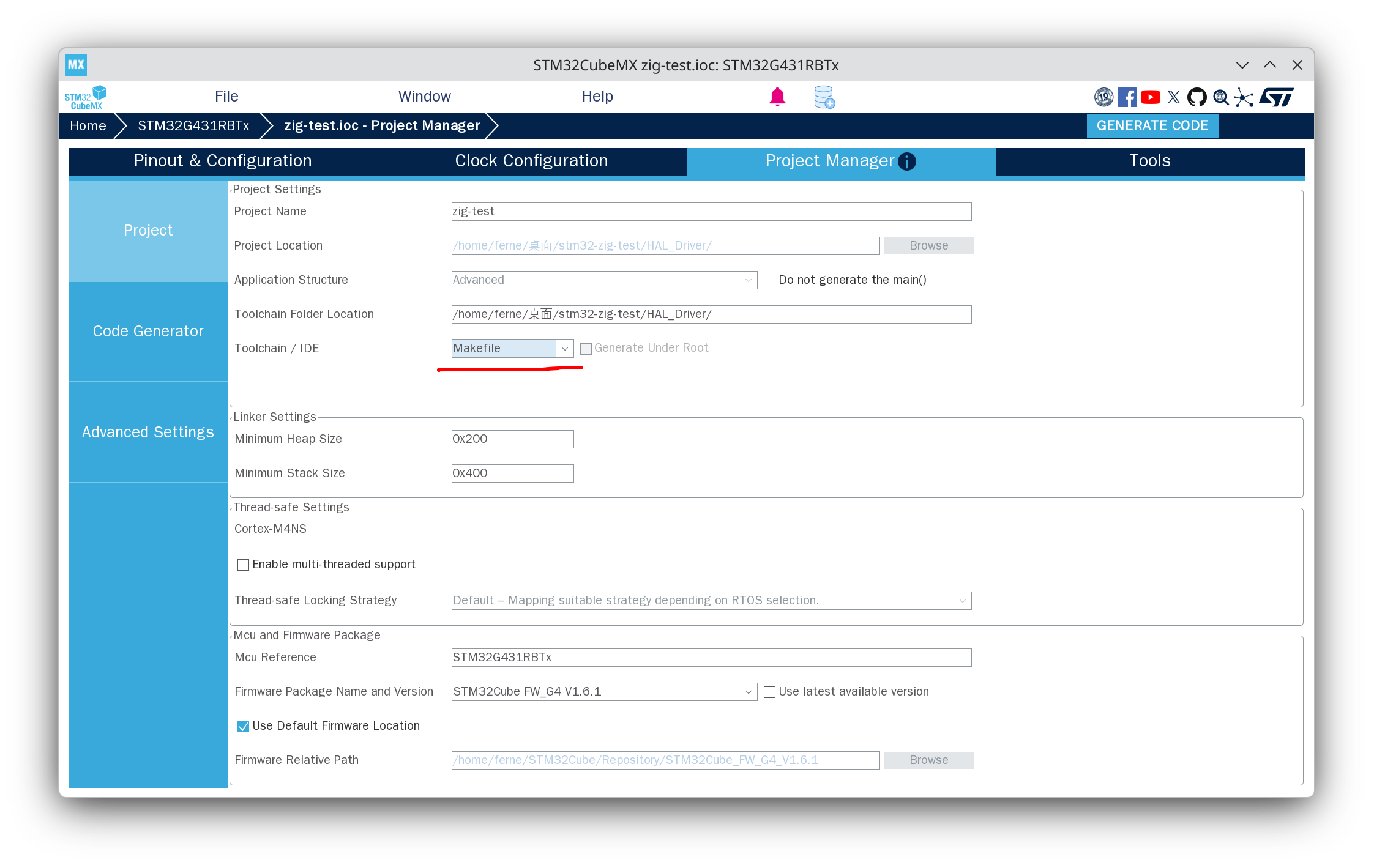
CubeMX 基础配置 选择 STM32G431RBT6 生成工程到指定位置(这一步应该不用我说吧),
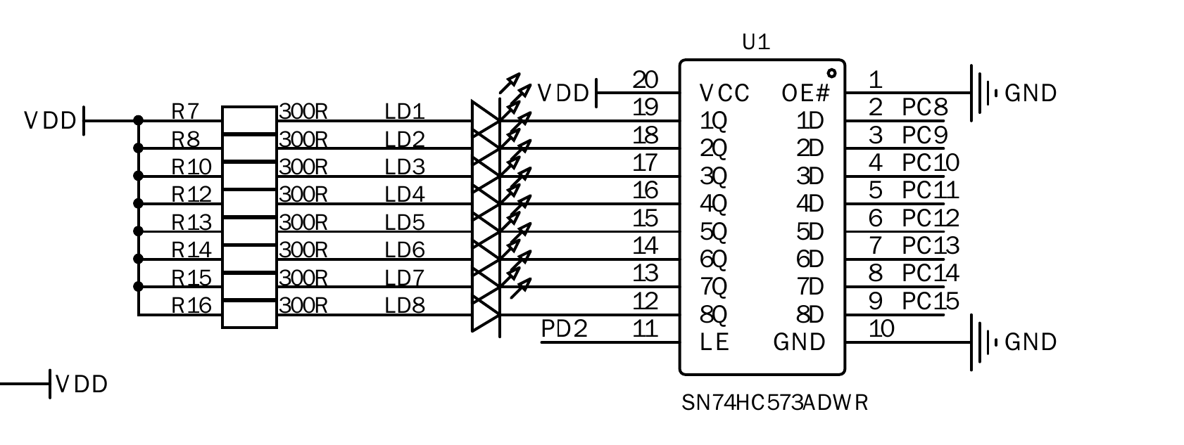
然后简单配置一下,我这里用的是蓝桥杯的板子,其实只要配几个 LED 就行:
LED 让它默认高电平,这样子 没那么晃眼 等会点灯现象明显一些:
Vscode 环境配置 然后打开 Vscode,选择 EIDE 并导入工程,
打开工作区之后侧边导航栏点开 EIDE:
项目资源点开 Application/MDK-ARM,
构建配置选择 GNU Arm Embedded Toolchain
链接脚本路径则填入 STM32G431XX_FLASH.ld 的相对路径
烧录配置选择 OpenOCD,并将芯片配置改为 stm32g4x.cfg,接口配置改为 cmsis-dap.cfg
然后再说到 Vscode 对 Debug 的支持,
1
2
3
4
5
6
7
8
9
10
11
12
13
14
15
16
17
18
19
20
21
22
23
24
25
26
27
28
29
30
31
32
33
34
35
36
37
38
39
40
{ "version" : "0.2.0" , "configurations" : [ { "cwd" : "${workspaceRoot}" , "executable" : "/path/to/zig-built/binary.elf" , "name" : "[DEBUG] zig ver" , "request" : "launch" , "type" : "cortex-debug" , "servertype" : "openocd" , "configFiles" : [ "interface/cmsis-dap.cfg" , "target/stm32g4x.cfg" ] , "searchDir" : [ ] , "runToEntryPoint" : "main" , "showDevDebugOutput" : "none" } , { "cwd" : "${workspaceRoot}" , "executable" : "/path/to/arm-gcc-built/binary.elf" , "name" : "[DEBUG] arm-gcc ver" , "request" : "launch" , "type" : "cortex-debug" , "servertype" : "openocd" , "configFiles" : [ "interface/cmsis-dap.cfg" , "target/stm32g4x.cfg" ] , "searchDir" : [ ] , "runToEntryPoint" : "main" , "showDevDebugOutput" : "none" } , ] }
如果你想要像 Keil 一样动态查看值(不过只能看值)的话,加入:
1
2
3
4
"liveWatch" : { "enabled" : true , "samplesPerSecond" : 4 } ,
如果你想要看外设寄存器的值,考虑装一个 Peripheral Viewer 插件,并导入 SVD 文件:
1 2 "svdPath" : "/path/to/STM32G431.svd" ,
不过现阶段导入 SVD 没什么用,我们下面要看的寄存器不在 SVD 文件的配置里。
这时正常来说就可以编译烧录了,应该同时也可以调试了(arm-gcc ver 的选项,zig 的还没配完)。
然后 MDK-ARM 你想保留也行,删掉也行,
加入点灯代码 接下来编辑 Core/Src/main.c 找到对应位置并加入如下代码:
宏定义:
这个你也可以在 EIDE 插件内选择 C/C++ 属性,
1 2 3 4 5 6 7 #define BUILD_BY_EIDE
外部函数声明:
1 2 3 4 5 6 #if defined(BUILD_BY_ZIG) && !defined(BUILD_BY_EIDE) extern void zigMain (void ) ; #endif
main 函数内部调用:
1 2 3 4 5 6 7 8 9 10 11 12 13 14 15 16 17 18 19 20 21 #if defined(BUILD_BY_ZIG) && !defined(BUILD_BY_EIDE) zigMain(); #endif while (1 ) { #if !defined(BUILD_BY_ZIG) && defined(BUILD_BY_EIDE) HAL_GPIO_WritePin(LED1_GPIO_Port, LED1_Pin, GPIO_PIN_RESET); HAL_Delay(1000 ); HAL_GPIO_WritePin(LED1_GPIO_Port, LED1_Pin, GPIO_PIN_SET); HAL_Delay(1000 ); #endif }
然后编辑 src/main.zig,删除默认代码并加入如下代码:
1
2
3
export fn zigMain () void { while (true ) {} }
Zig 项目初始化 如果你已经设置好了 Zig 的环境变量,cd 到你的工作区, zig init 一下就可以生成一个项目了。
build.zigbuild.zig.zonsrc/main.zigsrc/root.zig
其中 build.zig 起到类似 Makefile/CMake 的作用,但是完全由 Zig 书写,build.zig.zon 我还没研究过,貌似可以从 GitHub 导入外部库。
我们这里暂时不需要 src/root.zig,等会会改 build.zig,使之只使用 src/main.zig 的代码。
修改 build.zig 接下来我们就要开始写相当重量级的东西了,理解这个过程之后你对整个 STM32 生成项目的步骤都会有质的飞跃。
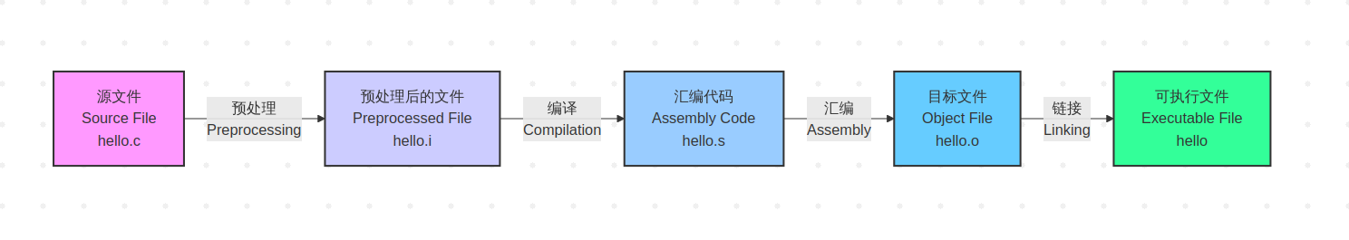
编译原理简单回顾 我们都知道,C 语言的编译生成二进制文件的过程分为:
预处理步骤就是简单的文本替换,我们不需要关心。
编译过程 会生成汇编码,这一步就会决定你的代码能在什么平台上跑,这是我们需要关心 的。汇编过程是生成机器码(二进制),我们不太需要关心。
链接过程 会将你的代码与其他二进制文件(lib, o 等)进行链接,extern 的外部函数/变量及预处理阶段产生的函数声明的实现。需要关心 的。
Zig 和 C ,以及各种多语言项目之所以可行,其实就在上面已经说明了。
观察 Makefile 让我们把 Makefile 的 BUILD_DIR 换成 build-make(防止覆盖 EIDE 默认的 build 目录)
接下来 cd 到 Makefile 的根目录下,执行 make -j$(nproc),观察命令输出:
下面是生成 obj 文件的过程(由于许多都是差不多的结构,因此只贴一个):
1 arm-none-eabi-gcc -c -mcpu=cortex-m4 -mthumb -mfpu=fpv4-sp-d16 -mfloat-abi=hard -DUSE_HAL_DRIVER -DSTM32G431xx -ICore/Inc -IDrivers/STM32G4xx_HAL_Driver/Inc -IDrivers/STM32G4xx_HAL_Driver/Inc/Legacy -IDrivers/CMSIS/Device/ST/STM32G4xx/Include -IDrivers/CMSIS/Include -Og -Wall -fdata-sections -ffunction-sections -g -gdwarf-2 -MMD -MP -MF"build-make/main.d" -Wa,-a,-ad,-alms=build-make/main.lst Core/Src/main.c -o build-make/main.o
下面是生成 elf 文件的过程(链接):
1 arm-none-eabi-gcc build-make/main.o build-make/gpio.o build-make/usart.o build-make/stm32g4xx_it.o build-make/stm32g4xx_hal_msp.o build-make/stm32g4xx_hal_pwr_ex.o build-make/stm32g4xx_hal_uart.o build-make/stm32g4xx_hal_uart_ex.o build-make/stm32g4xx_hal.o build-make/stm32g4xx_hal_rcc.o build-make/stm32g4xx_hal_rcc_ex.o build-make/stm32g4xx_hal_flash.o build-make/stm32g4xx_hal_flash_ex.o build-make/stm32g4xx_hal_flash_ramfunc.o build-make/stm32g4xx_hal_gpio.o build-make/stm32g4xx_hal_exti.o build-make/stm32g4xx_hal_dma.o build-make/stm32g4xx_hal_dma_ex.o build-make/stm32g4xx_hal_pwr.o build-make/stm32g4xx_hal_cortex.o build-make/system_stm32g4xx.o build-make/sysmem.o build-make/syscalls.o build-make/startup_stm32g431xx.o -mcpu=cortex-m4 -mthumb -mfpu=fpv4-sp-d16 -mfloat-abi=hard -specs=nano.specs -TSTM32G431XX_FLASH.ld -lc -lm -lnosys -Wl,-Map=build-make/zig-test.map,--cref -Wl,--gc-sections -o build-make/zig-test.elf
我们可以看到,arm-none-eabi-gcc 带有如下参数:
-Ixxx
-DUSE_HAL_DRIVER
-DSTM32G431xx
-mcpu=cortex-m4
-mthumb
-mfpu=fpv4-sp-d16
-mfloat-abi=hard
-specs=nano.specs
-TSTM32G431XX_FLASH.ld
-lc -lm -lnosys
-Wl, -Map=build-make/zig-test.map
–cref
-Wl, –gc-sections
然后我们来捋一下这里每个参数的作用(下面的表格让 AI 生成了一下)
参数
作用说明
-Ixxx 头文件搜索路径 xxx 目录下查找头文件(.h 文件)。通常用于包含工程中的驱动目录或中间件目录。
-DUSE_HAL_DRIVER 定义宏 USE_HAL_DRIVER 宏。这通常用于 STM32 HAL 库,告诉编译器启用 HAL 库相关的代码(stm32g4xx_hal_conf.h 中会检查此宏)。
-DSTM32G431xx 定义宏 STM32G431xx。这使得 HAL 库能够根据该型号包含特定的外设定义和初始化代码。
-mcpu=cortex-m4 目标 CPU
-mthumb 指令集
-mfpu=fpv4-sp-d16 FPU 类型
-mfloat-abi=hard 浮点 ABI hard。意味着浮点运算直接通过硬件 FPU 执行,且函数调用时浮点参数通过浮点寄存器传递,性能更高。
-specs=nano.specs 链接库规格 newlib-nano 库规格。这是针对嵌入式系统优化的精简版 C 标准库,代码体积更小。
-TSTM32G431XX_FLASH.ld 链接脚本 STM32G431XX_FLASH.ld 作为链接脚本文件。该脚本定义了代码和数据在 Flash 和 RAM 中的存储布局(如堆栈大小、段地址)。
-lc -lm -lnosys 链接库 -lc: C 标准库-lm: 数学库-lnosys: 也就是 libnosys.a,用于提供空的系统调用实现(防止链接报错)。
-Wl, -Map=build-make/zig-test.map 链接器参数:生成 MAP 文件 -Wl 表示将后面的参数传递给链接器。这里指示链接器生成名为 zig-test.map 的映射文件,用于查看内存占用和符号地址。
–cref 输出交叉引用表
-Wl, –gc-sections 链接器参数:删除无用段
我们刚才说到,要关心的主要是编译和链接两个过程,因此这里:
-mcpu, -mthumb, -mfpu, -mfloat-abi
-lc -sepcs=nano.specs, -lm, -lnosys, -TSTM32G431XX_FLASH.ld, -Wl –gc-sections
需要我们关注,其他的也要关注,但它们不是最主要的难点(试问添加头文件和宏定义谁不会呢?)
有了这些信息之后,我们要干的事情就很简单了,只要解决这些问题,理论上就可以用 zig 开发单片机了。
修改 build.zig, 编译、链接 先提醒一句,为了避免是 Zig 代码导致的灯不闪烁,现在启用的宏是 BUILD_BY_EIDE.
现在我们打开 build.zig,删掉多余的注释和 build 函数内的内容,然后添加如下内容:
1
2
3
4
5
6
7
8
9
10
11
12
13
14
15
16
17
18
19
20
21
22
23
24
25
26
27
28
29
30
31
32
33
34
35
36
37
38
39
40
41
42
43
44
45
46
47
48
49
50
51
52
53
54
55
56
57
58
59
60
61
62
63
64
65
66
67
68
69
70
71
72
73
74
75
76
77
78
79
80
81
82
83
84
85
86
87
88
89
90
91
92
93
94
95
96
97
98
99
100
101
102
103
104
105
106
107
108
109
110
111
112
113
114
115
116
117
118
119
120
121
122
123
124
125
126
127
128
129
130
131
132
133
134
135
136
137
138
139
140
141
142
143
144
145
146
147
148
149
150
151
152
153
154
155
156
157
158
const std = @import ("std" );pub fn build (b: *std.Build) void { const target = b.standardTargetOptions (.{ .default_target = .{ .cpu_arch = .thumb, .os_tag = .freestanding, .abi = .eabihf, .cpu_model = std.Target.Query.CpuModel{ .explicit = &std.Target.arm.cpu.cortex_m4 }, .cpu_features_add = std.Target.arm.featureSet ( &[_]std.Target.arm.Feature{}, ), }, }); const exec_name = "zig-test" ; const optimize = b.standardOptimizeOption (.{}); const mod = b.addModule (exec_name, .{ .root_source_file = b.path ("src/main.zig" ), .target = target, .optimize = optimize, .link_libc = false , .single_threaded = true , .sanitize_c = .off, }); const exe = b.addExecutable (.{ .name = exec_name ++ ".elf" , .root_module = mod , .linkage = .static , }); const arm_gcc_pgm = if (b.option ([]const u8 , "armgcc" , "Path to arm-none-eabi-gcc compiler" )) |arm_gcc_path| b.findProgram (&.{"arm-none-eabi-gcc" }, &.{arm_gcc_path}) catch { std.log.err ("Couldn't find arm-none-eabi-gcc at provided path: {s}\n" , .{arm_gcc_path}); unreachable; } else b.findProgram (&.{"arm-none-eabi-gcc" }, &.{}) catch { std.log.err ("Couldn't find arm-none-eabi-gcc in PATH, try manually providing the path to this executable with -Darmgcc=[path]\n" , .{}); unreachable; }; if (b.option (bool , "NEWLIB_PRINTF_FLOAT" , "Force newlib to include float support for printf()" )) |_| { exe.forceUndefinedSymbol("_printf_float" ); } const gcc_arm_sysroot_path = std.mem.trim (u8 , b.run (&.{ arm_gcc_pgm, "-print-sysroot" }), "\r\n" ); const gcc_arm_multidir_relative_path = std.mem.trim (u8 , b.run (&.{ arm_gcc_pgm, "-mcpu=cortex-m4" , "-mfloat-abi=hard" , "-print-multi-directory" }), "\r\n" ); const gcc_arm_version = std.mem.trim (u8 , b.run (&.{ arm_gcc_pgm, "-dumpversion" }), "\r\n" ); const gcc_arm_lib_path1 = b.fmt ("{s}/../lib/gcc/arm-none-eabi/{s}/{s}" , .{ gcc_arm_sysroot_path, gcc_arm_version, gcc_arm_multidir_relative_path }); const gcc_arm_lib_path2 = b.fmt ("{s}/lib/{s}" , .{ gcc_arm_sysroot_path, gcc_arm_multidir_relative_path }); mod .addLibraryPath (.{ .cwd_relative = gcc_arm_lib_path1 }); mod .addLibraryPath (.{ .cwd_relative = gcc_arm_lib_path2 }); mod .addSystemIncludePath (.{ .cwd_relative = b.fmt ("{s}/include" , .{gcc_arm_sysroot_path}) }); mod .linkSystemLibrary ("c_nano" , .{ .needed = true , .preferred_link_mode = .static , .use_pkg_config = .no, }); mod .linkSystemLibrary ("m" , .{ .needed = true , .preferred_link_mode = .static , .use_pkg_config = .no, }); mod .addObjectFile (.{ .cwd_relative = b.fmt ("{s}/crt0.o" , .{gcc_arm_lib_path2}) }); mod .addObjectFile (.{ .cwd_relative = b.fmt ("{s}/crti.o" , .{gcc_arm_lib_path1}) }); mod .addObjectFile (.{ .cwd_relative = b.fmt ("{s}/crtbegin.o" , .{gcc_arm_lib_path1}) }); mod .addObjectFile (.{ .cwd_relative = b.fmt ("{s}/crtend.o" , .{gcc_arm_lib_path1}) }); mod .addObjectFile (.{ .cwd_relative = b.fmt ("{s}/crtn.o" , .{gcc_arm_lib_path1}) }); const STM32_Driver_Path = "HAL_Driver" ; mod .addIncludePath (b.path (b.fmt ("{s}/Core/Inc" , .{STM32_Driver_Path}))); mod .addIncludePath (b.path (b.fmt ("{s}/Drivers/STM32G4xx_HAL_Driver/Inc" , .{STM32_Driver_Path}))); mod .addIncludePath (b.path (b.fmt ("{s}/Drivers/STM32G4xx_HAL_Driver/Inc/Legacy" , .{STM32_Driver_Path}))); mod .addIncludePath (b.path (b.fmt ("{s}/Drivers/CMSIS/Device/ST/STM32G4xx/Include" , .{STM32_Driver_Path}))); mod .addIncludePath (b.path (b.fmt ("{s}/Drivers/CMSIS/Include" , .{STM32_Driver_Path}))); mod .addAssemblyFile (b.path (b.fmt ("{s}/startup_stm32g431xx.s" , .{STM32_Driver_Path}))); mod .addCSourceFiles (.{ .files = &.{ b.fmt ("{s}/Core/Src/main.c" , .{STM32_Driver_Path}), b.fmt ("{s}/Core/Src/usart.c" , .{STM32_Driver_Path}), b.fmt ("{s}/Core/Src/gpio.c" , .{STM32_Driver_Path}), b.fmt ("{s}/Core/Src/stm32g4xx_it.c" , .{STM32_Driver_Path}), b.fmt ("{s}/Core/Src/stm32g4xx_hal_msp.c" , .{STM32_Driver_Path}), b.fmt ("{s}/Core/Src/system_stm32g4xx.c" , .{STM32_Driver_Path}), b.fmt ("{s}/Core/Src/sysmem.c" , .{STM32_Driver_Path}), b.fmt ("{s}/Core/Src/syscalls.c" , .{STM32_Driver_Path}), b.fmt ("{s}/Drivers/STM32G4xx_HAL_Driver/Src/stm32g4xx_hal.c" , .{STM32_Driver_Path}), b.fmt ("{s}/Drivers/STM32G4xx_HAL_Driver/Src/stm32g4xx_hal_pwr.c" , .{STM32_Driver_Path}), b.fmt ("{s}/Drivers/STM32G4xx_HAL_Driver/Src/stm32g4xx_hal_pwr_ex.c" , .{STM32_Driver_Path}), b.fmt ("{s}/Drivers/STM32G4xx_HAL_Driver/Src/stm32g4xx_hal_dma.c" , .{STM32_Driver_Path}), b.fmt ("{s}/Drivers/STM32G4xx_HAL_Driver/Src/stm32g4xx_hal_dma_ex.c" , .{STM32_Driver_Path}), b.fmt ("{s}/Drivers/STM32G4xx_HAL_Driver/Src/stm32g4xx_hal_gpio.c" , .{STM32_Driver_Path}), b.fmt ("{s}/Drivers/STM32G4xx_HAL_Driver/Src/stm32g4xx_hal_exti.c" , .{STM32_Driver_Path}), b.fmt ("{s}/Drivers/STM32G4xx_HAL_Driver/Src/stm32g4xx_hal_cortex.c" , .{STM32_Driver_Path}), b.fmt ("{s}/Drivers/STM32G4xx_HAL_Driver/Src/stm32g4xx_hal_rcc.c" , .{STM32_Driver_Path}), b.fmt ("{s}/Drivers/STM32G4xx_HAL_Driver/Src/stm32g4xx_hal_rcc_ex.c" , .{STM32_Driver_Path}), b.fmt ("{s}/Drivers/STM32G4xx_HAL_Driver/Src/stm32g4xx_hal_flash.c" , .{STM32_Driver_Path}), b.fmt ("{s}/Drivers/STM32G4xx_HAL_Driver/Src/stm32g4xx_hal_flash_ex.c" , .{STM32_Driver_Path}), b.fmt ("{s}/Drivers/STM32G4xx_HAL_Driver/Src/stm32g4xx_hal_flash_ramfunc.c" , .{STM32_Driver_Path}), b.fmt ("{s}/Drivers/STM32G4xx_HAL_Driver/Src/stm32g4xx_hal_uart.c" , .{STM32_Driver_Path}), b.fmt ("{s}/Drivers/STM32G4xx_HAL_Driver/Src/stm32g4xx_hal_uart_ex.c" , .{STM32_Driver_Path}), b.fmt ("{s}/Drivers/STM32G4xx_HAL_Driver/Src/stm32g4xx_hal_tim.c" , .{STM32_Driver_Path}), b.fmt ("{s}/Drivers/STM32G4xx_HAL_Driver/Src/stm32g4xx_hal_tim_ex.c" , .{STM32_Driver_Path}), }, }); mod .addCMacro ("USE_HAL_DRIVER" , "" ); mod .addCMacro ("STM32G431xx" , "" ); exe.link_gc_sections = true ; exe.link_data_sections = true ; exe.link_function_sections = true ; exe.setLinkerScript (b.path (b.fmt ("{s}/STM32G431XX_FLASH.ld" , .{STM32_Driver_Path}))); b.installArtifact (exe); }
理论上来说到这里,我们就可以开始 zig build 然后愉快地编译了。
但是等一下,为什么会报错?
1
2
3
4
5
6
7
8
9
❯ zig build install └─ install zig-test.elf └─ compile exe zig-test.elf Debug thumb-freestanding-eabihf 1 errors error: ld.lld: /home/ferne/桌面/stm32-zig-test/HAL_Driver/STM32G431XX_FLASH.ld:56: memory region not defined: RAM note: _estack = ORIGIN(RAM) + LENGTH(RAM); /* end of RAM */ note: ^ error: the following command failed with 1 compilation errors: ...
可以看到是链接文件的问题,它提示我们 RAM 这个内存区域没有定义,那么我们来看一下 CubeMX 生成的 ld 文件:
修改 STM32G431XX_FLASH.ld,链接 我们来看这一段:
1
2
3
4
5
6
7
8
9
10
11
12
13
14
15
/* Entry Point */ ENTRY(Reset_Handler) /* Highest address of the user mode stack */ _estack = ORIGIN(RAM) + LENGTH(RAM); /* end of RAM */ /* Generate a link error if heap and stack don't fit into RAM */ _Min_Heap_Size = 0x200; /* required amount of heap */ _Min_Stack_Size = 0x400; /* required amount of stack */ /* Specify the memory areas */ MEMORY { RAM (xrw) : ORIGIN = 0x20000000, LENGTH = 32K FLASH (rx) : ORIGIN = 0x8000000, LENGTH = 128K }
可以看到是定义了 RAM 的,但是是在使用之后定义的,这是很典型的前向引用问题,修改一下就好了:
1
2
3
4
5
6
7
8
9
10
11
12
13
14
15
/* Entry Point */ ENTRY(Reset_Handler) /* Specify the memory areas */ MEMORY { RAM (xrw) : ORIGIN = 0x20000000, LENGTH = 32K FLASH (rx) : ORIGIN = 0x8000000, LENGTH = 128K } /* Highest address of the user mode stack */ _estack = ORIGIN(RAM) + LENGTH(RAM); /* end of RAM */ /* Generate a link error if heap and stack don't fit into RAM */ _Min_Heap_Size = 0x200; /* required amount of heap */ _Min_Stack_Size = 0x400; /* required amount of stack */
然后再 build,发现更多的问题:
1
2
3
4
5
6
7
8
❯ zig build install └─ install zig-test.elf └─ compile exe zig-test.elf Debug thumb-freestanding-eabihf 29 errors error: ld.lld: /home/ferne/桌面/stm32-zig-test/HAL_Driver/STM32G431XX_FLASH.ld:106: symbol not found: READONLY error: ld.lld: /home/ferne/桌面/stm32-zig-test/HAL_Driver/STM32G431XX_FLASH.ld:113: symbol not found: READONLY error: ld.lld: /home/ferne/桌面/stm32-zig-test/HAL_Driver/STM32G431XX_FLASH.ld:122: symbol not found: READONLY ...
我个人推测是因为 zig 的编译器 zig cc 没有实现 GCC11 及更高版本所支持的 READONLY 关键字,READONLY 的部分,然后再 zig build。
好,构建成功!
1
2
3
4
❯ zig build ❯ echo $? 0
但是这就完事了吗?来,我们烧录进去看一下。
1
2
3
4
5
6
7
8
9
10
11
12
13
14
15
16
17
18
19
20
21
22
23
24
25
26
27
28
29
30
31
32
33
34
35
36
37
38
39
40
❯ /usr/bin/openocd -s "/path/to/your/project" -f "interface/cmsis-dap.cfg" -f "target/stm32g4x.cfg" -c "program \"/path/to/your/binary.elf\" verify " -c "reset run" -c "exit" Open On-Chip Debugger 0.12.0-01004-g9ea7f3d64-dirty (2025-11-12-08:18) Licensed under GNU GPL v2 For bug reports, read http://openocd.org/doc/doxygen/bugs.html Info : auto-selecting first available session transport "swd" . To override use 'transport select <transport>' . Info : CMSIS-DAP: SWD supported Info : CMSIS-DAP: JTAG supported Info : CMSIS-DAP: FW Version = 1.0 Info : CMSIS-DAP: Interface Initialised (SWD) Info : SWCLK/TCK = 1 SWDIO/TMS = 1 TDI = 1 TDO = 1 nTRST = 0 nRESET = 1 Info : CMSIS-DAP: Interface ready Info : clock speed 2000 kHz Info : SWD DPIDR 0x2ba01477 Info : [stm32g4x.cpu] Cortex-M4 r0p1 processor detected Info : [stm32g4x.cpu] target has 6 breakpoints, 4 watchpoints Info : starting gdb server for stm32g4x.cpu on 3333 Info : Listening on port 3333 for gdb connections [stm32g4x.cpu] halted due to debug-request, current mode: Thread xPSR: 0x01000000 pc: 0x08000468 msp: 0x20008000 ** Programming Started ** Info : device idcode = 0x20036468 (STM32G43/G44xx - Rev 'unknown' : 0x2003) Info : RDP level 0 (0xAA) Info : flash size = 128 KiB Info : flash mode : single-bank Info : Padding image section 3 at 0x080033e4 with 4 bytes (bank write end alignment) Warn : Adding extra erase range, 0x080033e8 .. 0x080037ff Info : device idcode = 0x20036468 (STM32G43/G44xx - Rev 'unknown' : 0x2003) Info : RDP level 0 (0xAA) Info : OTP size is 1024 bytes, base address is 0x1fff7000 Warn : no flash bank found for address 0x2000005c ** Programming Finished ** ** Verify Started ** Error: checksum mismatch - attempting binary compare embedded:startup.tcl:1516: Error: ** Verify Failed ** Traceback (most recent call last): File "embedded:startup.tcl" , line 1577, in program program_error {** Verify Failed **} 0 File "embedded:startup.tcl" , line 1516, in program_error error {** Verify Failed **}
看下报错,发现有两处:
Warn : no flash bank found for address 0x2000005c
embedded:startup.tcl:1516: Error: ** Verify Failed **
一是 no flash bank,二是 Verify Failed,让我们去掉 verify 再试一次:
1
2
3
4
5
6
7
8
9
❯ /usr/bin/openocd -s "/path/to/your/project" -f "interface/cmsis-dap.cfg" -f "target/stm32g4x.cfg" -c "program \"/path/to/your/binary.elf\" " -c "reset run" -c "exit" ... Info : Padding image section 3 at 0x080033e4 with 4 bytes (bank write end alignment) Warn : Adding extra erase range, 0x080033e8 .. 0x080037ff Info : device idcode = 0x20036468 (STM32G43/G44xx - Rev 'unknown' : 0x2003) Info : RDP level 0 (0xAA) Info : OTP size is 1024 bytes, base address is 0x1fff7000 Warn : no flash bank found for address 0x2000005c ** Programming Finished **
为何 HardFault ? 首先我想提醒的是,一定注意是小端序的,不要读错内存了!小端序是低位放在低地址的!
如果你很懒,不想看一大段分析,那么可以从这里 跳转到最后看解决方案。
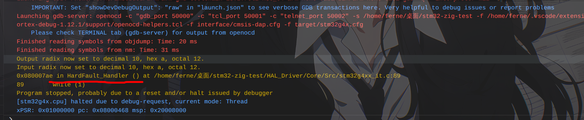
事故现场分析 发现虽然还有 Warn,但至少烧录成功了。BUILD_BY_EIDE,这就确保了不会是 Zig 代码的问题,
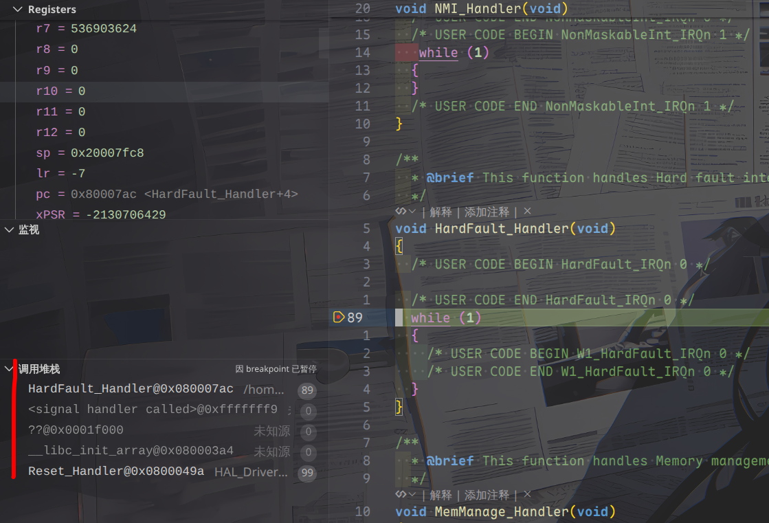
什么情况?怎么触发 HardFault 了?
可以看到这里的调用堆栈显示进入 HardFault 的过程是:
1
2
3
4
5
Reset_Handler@0x0800049a -> __libc_init_array@0x080003a4 -> ??@0x0001f000 -> <signal handler called>@0xfffffff9 -> HardFault_Handler@0x080007ac
因此肯定是上面的某个函数出了什么问题而导致的 HardFault,HardFault 可能出现的原因。
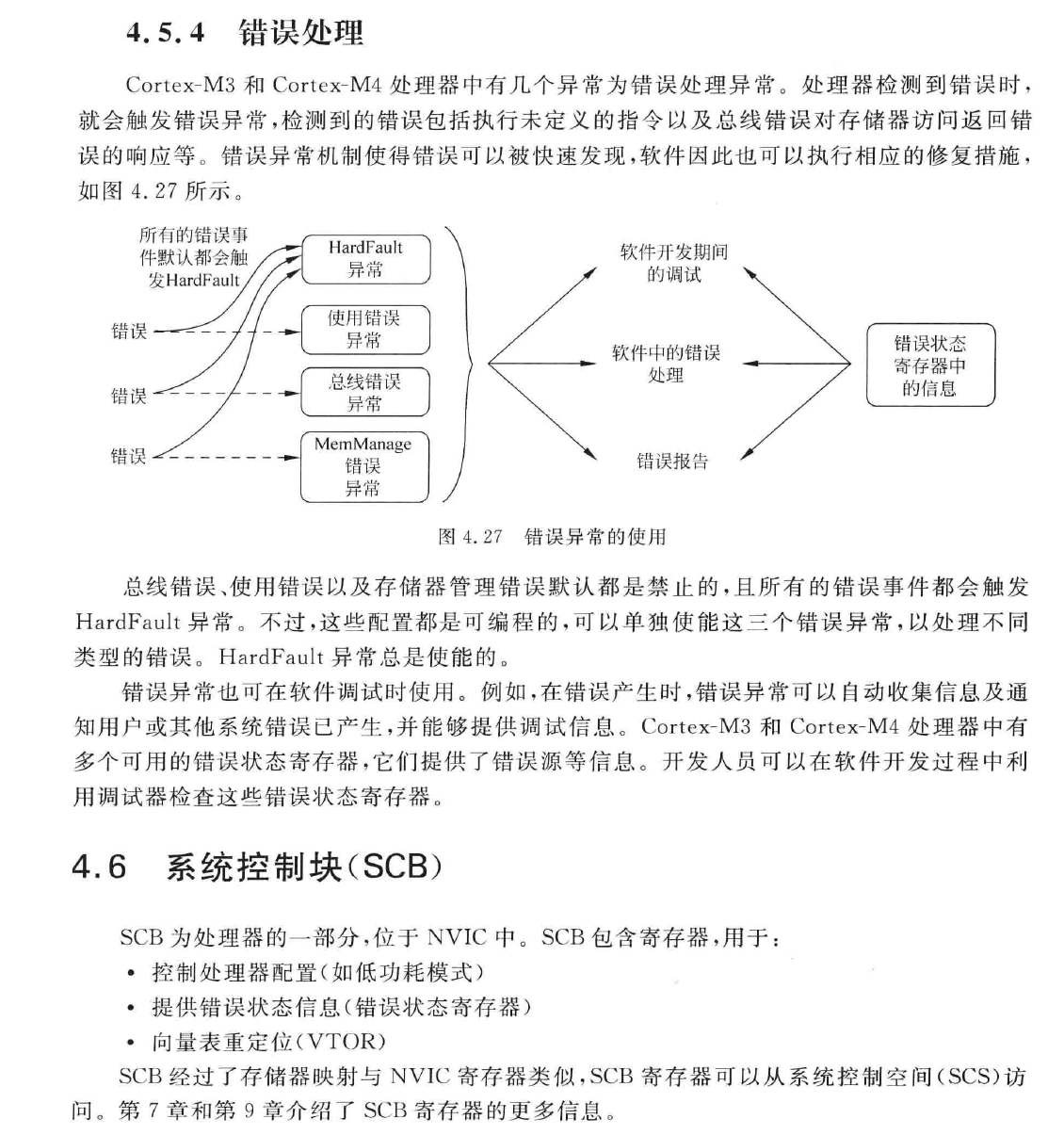
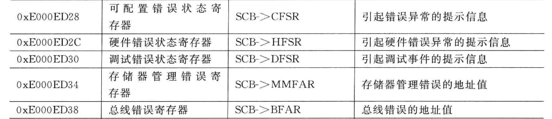
下文引自清华大学出版社出版的 Cortex-M4 权威指南:
可以看到 HardFault 是各种错误都有可能的,这确实加大了排查难度。__libc_init_array,看着就像是和数组/内存的非法访问有关。
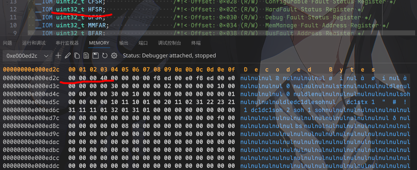
可以看到这个是和 HardFault 有关的寄存器,也许我们能从这里找到点灵感。0xe000ed2c,可以看到:
显示的 C 文件是 core_cm4.c,可以经由 stm32g4xx_hal_cortex.c 中任意对 NVIC 操作的宏函数定位到该文件。uint32_t HFSR 位于 SCB_Type 结构体中,0x4000 0000(时刻注意,是小端序 !)
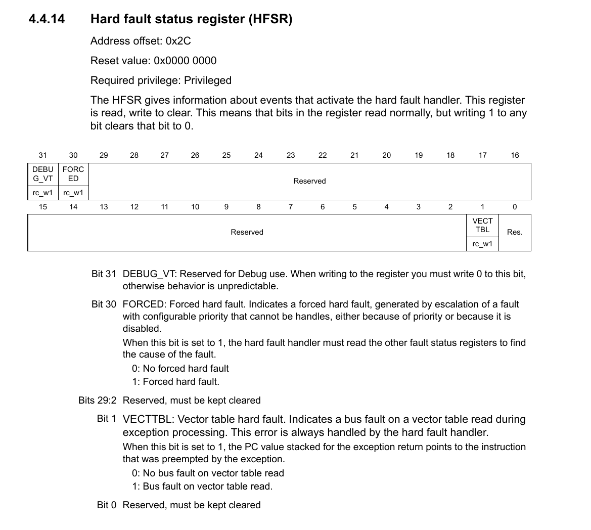
可以看到这里是因为某些原因写入了第 30 位(FORCED)所导致的 HardFault,HardFault 了,但是并没有说明具体是什么原因导致的,我们还得再找找。
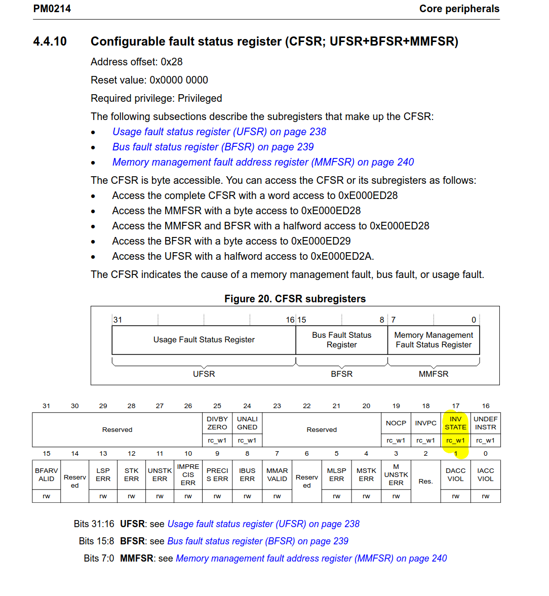
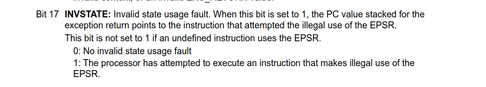
我们还注意到了有个 CFSR,看下是否有什么提示信息。0x0002 0000,也就是第 17 个 bit 被写入:
错误原因:
Invalid state usage fault. When this bit is set to 1, the PC value stacked for the exception return points to the instruction that attempted the illegal use of the EPSR.
EPSR: Execution program status register
因此这看起来像是错误调用了什么函数,执行到了某条错误的指令(因为和 PC 有关),Reset_Handler 和 __libc_init_array 是存在的,HardFault_Handler 是存在的,但是我们看不到 __libc_init_array 的实现,
我们再查阅一下 Cortex M4 权威指南,看下还有没有关于 SCB 的更多信息,
这里提到了 EPSR,因此需要查看一下寄存器操作。博客 。0x8100 0003(调试中的 Register 提示),
N:小于或等于标志( 0x8… )
工作在 thumb 指令集(-mthumb, 0x81… 的 1 表示为 thumb 指令集)
发生了 HardFault(末尾数字是 3,指示为 HardFault)
这似乎并不能给我们提供什么有用的信息,HardFault 之前做了一下减法运算,
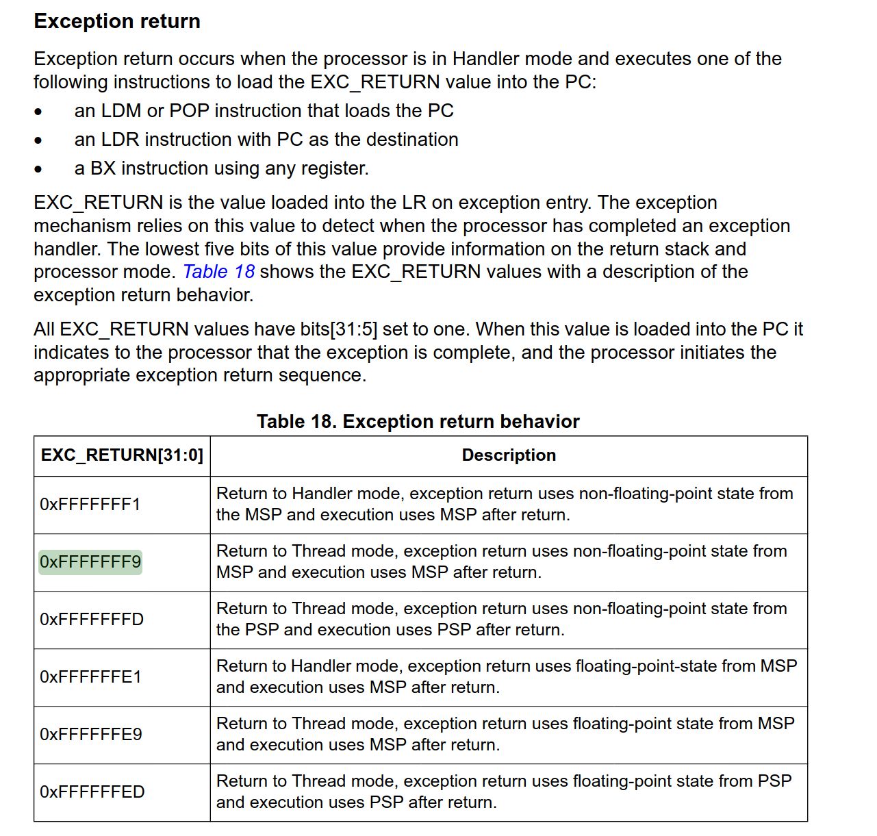
我们再次回到官方的编程手册,其中 EXEC_RETURN 中似乎指示了什么数字:
这里提到了 0xFFFF FFF9,似乎很眼熟,我们回到调用堆栈:
1
2
3
4
... ??@0x0001f000 -> <signal handler called>@0xfffffff9 -> ...
看到了吗,这里有一个 0xFFFF FFF9,让我们看下上面的解释。
返回至线程模式,异常返回过程将使用主堆栈(MSP) 中保存的非浮点状态,且返回后的程序执行也将继续使用主堆栈(MSP)。
这说明产生了异常,并且此时硬件自动压栈,产生了这个魔数,现在我们没有更多信息了,那让我们整理一下已有的信息吧。
故障信息汇总
程序执行流程为 Reset_Handler –> __libc_init_array –> ?? –> 状态切换 –> HardFault_Handler
可能是由于错误的函数调用(执行了某个非法地址的函数,其中疑点是 ?? 所代表的 PC 地址)导致了 HardFault
我们接下来对应的解题思路是:
对 __libc_init_array 进行反汇编,看下是否有可疑之处
查找 ?? 所代表的 PC 地址在 Cortex M4 的内存映射中是什么
程序启动流程 如果到了现在,你依然认为烧进去的程序第一个从 main 函数开始的话,那我也不知道说什么了。
很显然,启动顺序应该是:
1 Reset_Handler --> SystemInit --> <Some functions for initialzing data> --> __libc_init_array --> main
这一段通过对 startup_stm32g431xx.s 的分析即可得知,__libc_init_array 往后,__libc_init_array 处炸掉。源码实现 :
1 2 3 4 5 6 7 8 9 10 11 12 13 14 15 16 17 18 19 20 21 22 23 24 25 26 27 28 extern void (*__preinit_array_start []) (void ) __attribute__ ((weak)) ;extern void (*__preinit_array_end []) (void ) __attribute__ ((weak)) ;extern void (*__init_array_start []) (void ) __attribute__ ((weak)) ;extern void (*__init_array_end []) (void ) __attribute__ ((weak)) ;extern void (*__fini_array_start []) (void ) __attribute__ ((weak)) ;extern void (*__fini_array_end []) (void ) __attribute__ ((weak)) ;extern void _init (void );extern void _fini (void );void __libc_init_array (void ) { size_t count; size_t i; count = __preinit_array_end - __preinit_array_start; for (i = 0 ; i < count; i++) __preinit_array_start[i] (); _init (); count = __init_array_end - __init_array_start; for (i = 0 ; i < count; i++) __init_array_start[i] (); }
给某些不太清楚这玩意是干啥的读者介绍一下:__libc_init_array 函数是一个关键的启动时调用,main 函数之前被调用,确保所有必要的系统和库初始化都已完成。
由于我找到了两个来源(第二个 ),_init() 哪里有问题了。
对 zig 和 gcc 构建的两种二进制产物的逆向分析 我们接下来开始尝试分析这两个二进制文件的异同,看下究竟是什么导致的问题。__libc_init_array,这是需要重点排查的。
初始设定 为了简化操作,我们临时给一堆东西赋个值。
1
2
3
4
5
6
7
8
❯ ac_pre=arm-none-eabi ❯ acc=$ac_pre -gcc ❯ aod=$ac_pre -objdump ❯ are=$ac_pre -readelf ❯ anm=$ac_pre -nm ❯ aoc=$ac_pre -objcopy ❯ make_elf=HAL_Driver/build-make/zig-test.elf ❯ zig_elf=zig-out/bin/zig-test.elf
文件头分析 1 2 3 4 5 6 7 8 9 10 11 12 13 14 15 16 17 18 19 20 21 22 23 24 25 ❯ $are -h $make_elf ELF Header: Magic: 7f 45 4c 46 01 01 01 00 00 00 00 00 00 00 00 00 Class: ELF32 Data: 2's complement, little endian Version: 1 (current) OS/ABI: UNIX - System V ABI Version: 0 Type: EXEC (Executable file) Machine: ARM Version: 0x1 Entry point address: 0x8001ba9 Start of program headers: 52 (bytes into file) Start of section headers: 196448 (bytes into file) Flags: 0x5000400, Version5 EABI, hard-float ABI Size of this header: 52 (bytes) Size of program headers: 32 (bytes) Number of program headers: 3 Size of section headers: 40 (bytes) Number of section headers: 22 Section header string table index: 21
1 2 3 4 5 6 7 8 9 10 11 12 13 14 15 16 17 18 19 20 21 ❯ $are -h $zig_elf ELF Header: Magic: 7f 45 4c 46 01 01 01 00 00 00 00 00 00 00 00 00 Class: ELF32 Data: 2's complement, little endian Version: 1 (current) OS/ABI: UNIX - System V ABI Version: 0 Type: EXEC (Executable file) Machine: ARM Version: 0x1 Entry point address: 0x8000251 Start of program headers: 52 (bytes into file) Start of section headers: 1156992 (bytes into file) Flags: 0x5000400, Version5 EABI, hard-float ABI Size of this header: 52 (bytes) Size of program headers: 32 (bytes) Number of program headers: 9 Size of section headers: 40 (bytes) Number of section headers: 30 Section header string table index: 28
可以看到两者基本都相同:elf 文件,ARM 架构,32 位,小端序,硬浮点数…。0x0800 0000 以后即可(这和 Cortex M4 的复位启动流程有关,见下文 )
内存分析 1 2 3 4 5 6 7 8 9 10 11 12 13 14 15 16 17 ❯ $are -l $make_elf Elf file type is EXEC (Executable file) Entry point 0x8001ba9 There are 3 program headers, starting at offset 52 Program Headers: Type Offset VirtAddr PhysAddr FileSiz MemSiz Flg Align LOAD 0x001000 0x08000000 0x08000000 0x01fd4 0x01fd4 R E 0x1000 LOAD 0x003000 0x20000000 0x08001fd4 0x0000c 0x000a4 RW 0x1000 LOAD 0x0000a4 0x200000a4 0x08001fe0 0x00000 0x00604 RW 0x1000 Section to Segment mapping: Segment Sections... 00 .isr_vector .text .rodata .ARM.exidx.text.__udivmoddi4 01 .data .bss 02 ._user_heap_stack
1 2 3 4 5 6 7 8 9 10 11 12 13 14 15 16 17 18 19 20 21 22 23 24 25 26 27 28 29 ❯ $are -l $zig_elf Elf file type is EXEC (Executable file) Entry point 0x8000251 There are 9 program headers, starting at offset 52 Program Headers: Type Offset VirtAddr PhysAddr FileSiz MemSiz Flg Align LOAD 0x010000 0x08000000 0x08000000 0x00248 0x00248 R 0x10000 LOAD 0x010248 0x08000248 0x08000248 0x030ec 0x030ec R E 0x10000 LOAD 0x013334 0x08003334 0x08003334 0x00064 0x00064 R 0x10000 LOAD 0x020000 0x20000000 0x08003398 0x0005c 0x0005c RW 0x10000 LOAD 0x02005c 0x2000005c 0x2000005c 0x007fc 0x007fc RW 0x10000 GNU_RELRO 0x020850 0x20000850 0x20000850 0x00008 0x00008 R 0x1 GNU_EH_FRAME 0x01338c 0x0800338c 0x0800338c 0x0000c 0x0000c R 0x4 GNU_STACK 0x000000 0x00000000 0x00000000 0x00000 0x1000000 RW 0 ARM_EXIDX 0x0101d8 0x080001d8 0x080001d8 0x00070 0x00070 R 0x4 Section to Segment mapping: Segment Sections... 00 .isr_vector .ARM.exidx 01 .text 02 .rodata .ARM.extab.text.HAL_RCC_OscConfig .ARM.extab.text.__udivmoddi4 .eh_frame_hdr 03 .data 04 .tm_clone_table .bss ._user_heap_stack .init_array .fini_array 05 .init_array .fini_array 06 .eh_frame_hdr 07 08 .ARM.exidx
此时我们需要注意了,zig_elf 的版本里面似乎出现了许多我们在 make_elf 中没看到的东西,
注意 .init_array 和 .fini_array,从名字中可以看出它肯定和函数调用有点关系。
此外我们还观察到了一点:
反汇编分析 接下来我们来抓包 __libc_init_array:
1 2 3 4 5 ❯ $aod -S $zig_elf | grep -i "__libc_init_array" 8000292: f000 f86d bl 8000370 <__libc_init_array> 08000370 <__libc_init_array>: ... 8000496: f7ff ff6b bl 8000370 <__libc_init_array>
1 2 3 4 5 6 7 8 9 10 11 12 13 14 15 16 17 18 19 20 21 22 23 24 25 26 27 28 ❯ $aod -S $zig_elf | grep -A 26 -i "<__libc_init_array>:" 08000370 <__libc_init_array>: 8000370: b570 push {r4, r5, r6, lr} 8000372: 4b0d ldr r3, [pc, 8000374: 4c0d ldr r4, [pc, 8000376: 2600 movs r6, 8000378: 1b1d subs r5, r3, r4 800037a: ebb6 0fa5 cmp.w r6, r5, asr 800037e: d109 bne.n 8000394 <__libc_init_array+0x24> 8000380: f002 ffc4 bl 800330c <_init> 8000384: 4c0a ldr r4, [pc, 8000386: 4b0b ldr r3, [pc, 8000388: 2600 movs r6, 800038a: 1b1d subs r5, r3, r4 800038c: ebb6 0fa5 cmp.w r6, r5, asr 8000390: d105 bne.n 800039e <__libc_init_array+0x2e> 8000392: bd70 pop {r4, r5, r6, pc} 8000394: f854 3b04 ldr.w r3, [r4], 8000398: 4798 blx r3 800039a: 3601 adds r6, 800039c: e7ed b.n 800037a <__libc_init_array+0xa> 800039e: f854 3b04 ldr.w r3, [r4], 80003a2: 4798 blx r3 80003a4: 3601 adds r6, 80003a6: e7f1 b.n 800038c <__libc_init_array+0x1c> ... 80003b0: 20000850 .word 0x20000850 80003b4: 20000854 .word 0x20000854
从上面的反汇编看来,我之前找到的源码基本是八九不离十的,bl _init(调用 _init 函数),看下 _init 函数又做了什么:
1 2 3 4 5 6 7 8 9 10 11 12 13 14 15 16 ❯ $aod -S $zig_elf | grep -A 20 -i "<_init>:" 0800330c <_init>: 800330c: b5f8 push {r3, r4, r5, r6, r7, lr} 800330e: bf00 nop 8003310: bcf8 pop {r3, r4, r5, r6, r7} 8003312: bc08 pop {r3} 8003314: 469e mov lr, r3 8003316: 4770 bx lr 08003318 <_fini>: 8003318: b5f8 push {r3, r4, r5, r6, r7, lr} 800331a: bf00 nop 800331c: bcf8 pop {r3, r4, r5, r6, r7} 800331e: bc08 pop {r3} 8003320: 469e mov lr, r3 8003322: 4770 bx lr
然后我们看下 makefile 生成的:
1 2 3 4 5 6 7 8 9 10 11 12 13 14 15 16 17 18 19 20 21 22 23 24 25 26 ❯ $aod -S $make_elf | grep -A 26 -i "<__libc_init_array>:" 08001c0c <__libc_init_array>: 8001c0c: b570 push {r4, r5, r6, lr} 8001c0e: 4b0d ldr r3, [pc, 8001c10: 4c0d ldr r4, [pc, 8001c12: 2600 movs r6, 8001c14: 1b1d subs r5, r3, r4 8001c16: ebb6 0fa5 cmp.w r6, r5, asr 8001c1a: d109 bne.n 8001c30 <__libc_init_array+0x24> 8001c1c: f000 f9aa bl 8001f74 <_init> 8001c20: 4c0a ldr r4, [pc, 8001c22: 4b0b ldr r3, [pc, 8001c24: 2600 movs r6, 8001c26: 1b1d subs r5, r3, r4 8001c28: ebb6 0fa5 cmp.w r6, r5, asr 8001c2c: d105 bne.n 8001c3a <__libc_init_array+0x2e> 8001c2e: bd70 pop {r4, r5, r6, pc} 8001c30: f854 3b04 ldr.w r3, [r4], 8001c34: 4798 blx r3 8001c36: 3601 adds r6, 8001c38: e7ed b.n 8001c16 <__libc_init_array+0xa> 8001c3a: f854 3b04 ldr.w r3, [r4], 8001c3e: 4798 blx r3 8001c40: 3601 adds r6, 8001c42: e7f1 b.n 8001c28 <__libc_init_array+0x1c> ...
1 2 3 4 5 6 7 8 9 10 11 12 13 14 15 16 ❯ $aod -S $make_elf | grep -A 20 -i "<_init>:" 08001f74 <_init>: 8001f74: b5f8 push {r3, r4, r5, r6, r7, lr} 8001f76: bf00 nop 8001f78: bcf8 pop {r3, r4, r5, r6, r7} 8001f7a: bc08 pop {r3} 8001f7c: 469e mov lr, r3 8001f7e: 4770 bx lr 08001f80 <_fini>: 8001f80: b5f8 push {r3, r4, r5, r6, r7, lr} 8001f82: bf00 nop 8001f84: bcf8 pop {r3, r4, r5, r6, r7} 8001f86: bc08 pop {r3} 8001f88: 469e mov lr, r3 8001f8a: 4770 bx lr
对比上面两个汇编,发现什么了吗?对,zig 构建的版本有 __init_array_start 数组:
1 2 80003b0: 20000850 .word 0x20000850 80003b4: 20000854 .word 0x20000854
显然我们需要知道这两处地方到底存了什么东西,因为上面 __libc_init_array 调用了这里的内容,
回到我们提过的 .init_array 和 .fini_array,看来我们现在要看的是链接阶段产生的 .section 了。STM32G431XX_FLASH.ld 是否有定义这两个东西呢?肯定是没有的。zig cc 会把它制造出来呢?这可能就是 zig 内部的默认实现了。zig 默认会把这东西放哪里呢?不好说,所以这里我们到时候肯定要琢磨一下重写掉。
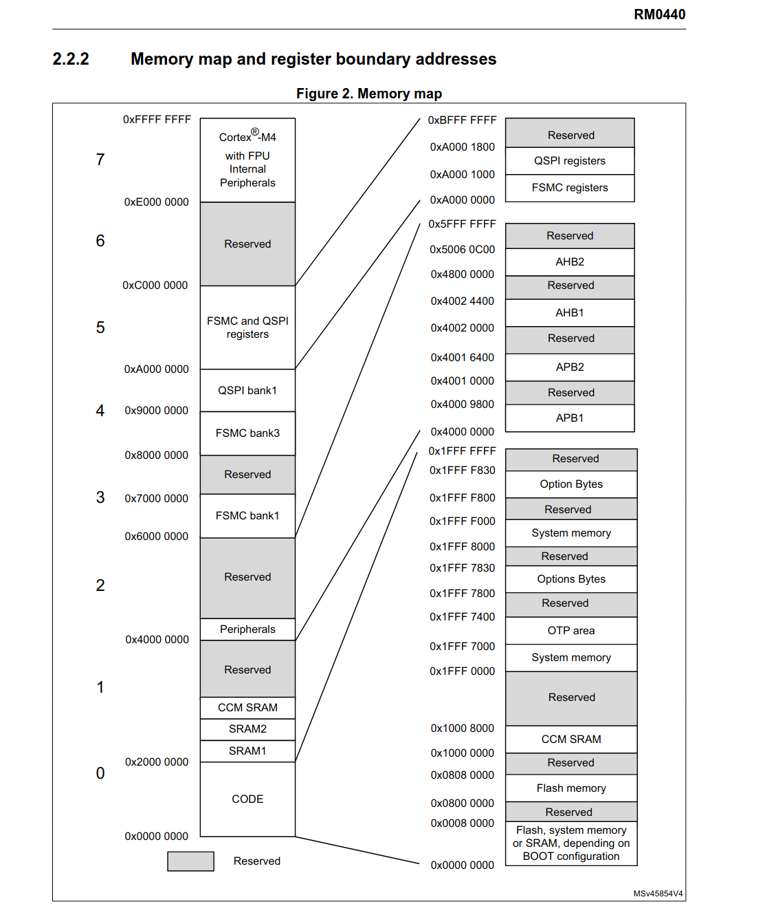
“拆除 HardFault 炸弹” 观察错误的 PC 值 我们现在锁定了问题,在 __init_array_start 数组中到底存在什么东西???@0x0001f000,这个在 STM32 中对应是什么内存区域呢:
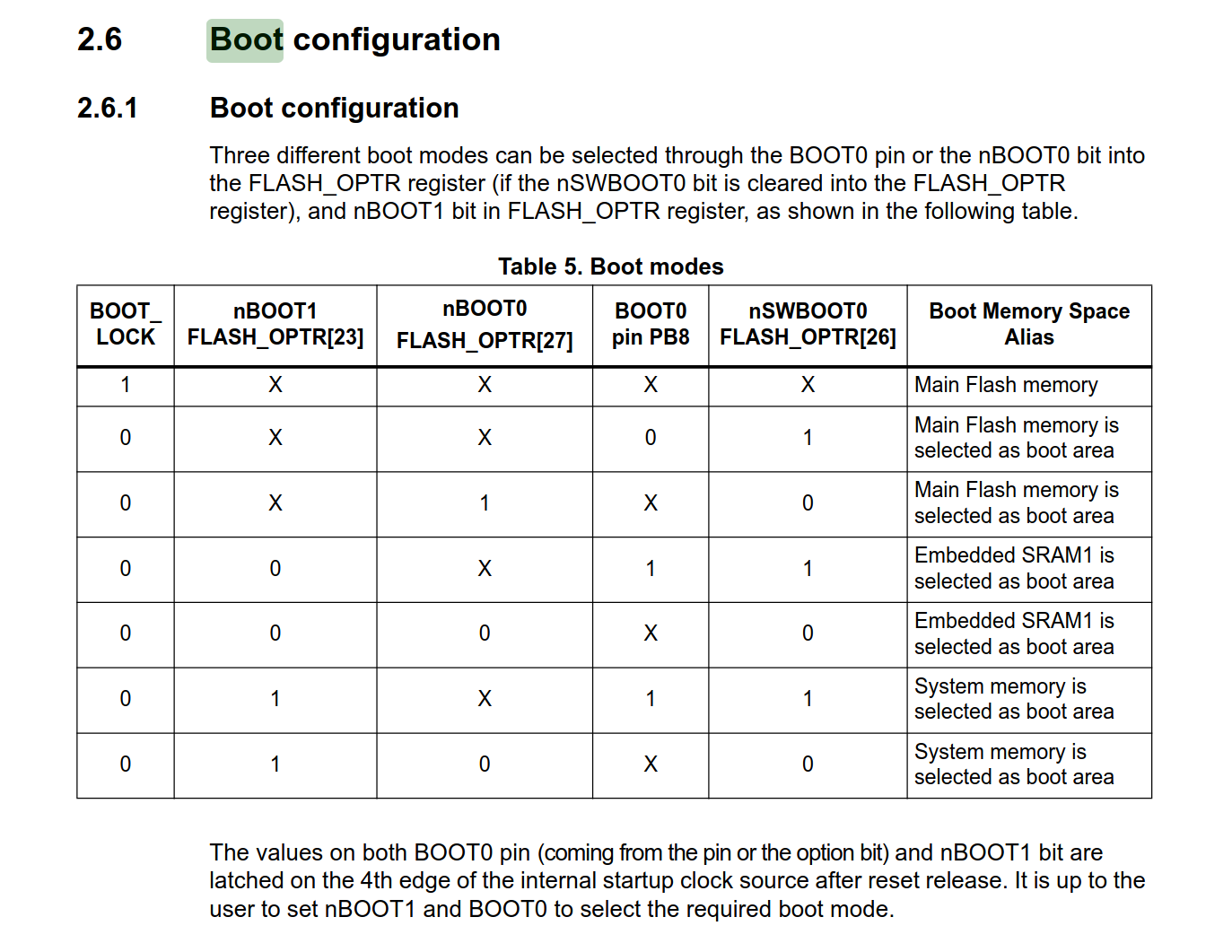
我们发现,0x0001 f000 属于:
Flash, system memory or SRAM, depending on BOOT configuration
根据蓝桥杯板子的 BOOT0 引脚配置,可以得知现在是主存作为 boot 引导区域(这似乎是废话)
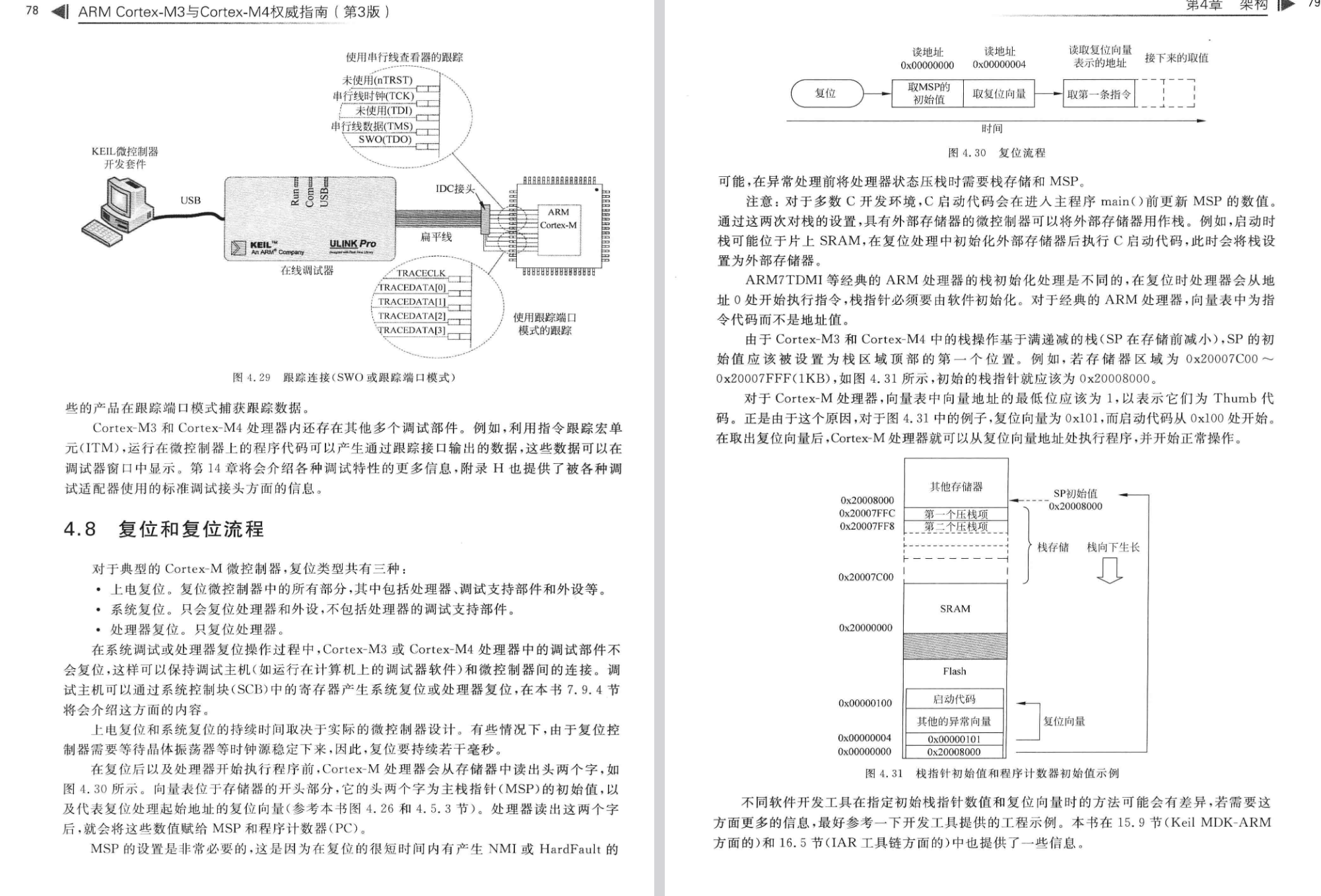
Cortex M4 启动流程 但问题是,Cortex-M4 的复位启动流程是什么?0x0800 xxxx 执行的代码,怎么一下子跳到 0x0001 ffff 了?
所以我们可以发现,一开始读取 SP 之后就会跳转到对应的地方去执行代码。0x0800 0251,0x0001 ffff,那么很显然就是函数调用出现问题。
但是,为什么函数的入口点就会在 0x0800 0251 呢?为什么不可以从 0x000 0008 开始呢?
链接脚本 (.ld/.lds) 简介 那么链接脚本是干什么的?或者说在裸机环境下如何构造内存布局?
如果你曾经学习过编译原理和操作系统相关的知识的话,
但是在裸机环境下,并不存在这样的模块(Cortex-M4 复位后会从 0x0000 0000 开始执行),
向量表(.isr_vector)位于 Flash 起始地址 0x0800 0000
代码段(.text)紧随其后
数据段(.data)和 BSS 段(.bss)位于 SRAM
栈和堆的位置和大小符合要求
因此我们需要用到链接脚本,链接脚本会告诉链接器应该怎么分配整合各个汇编阶段生成的二进制文件,
顺带说一下:
VMA(Virtual Memory Address):程序运行时的地址(即 VirtualAddr)
LMA(Load Memory Address):程序加载时的地址(即 PhysicAddr)文档
我们来分析一下 STM32CubeMX 生成的链接脚本,以辅助大家理解。
下面这段表示程序将从 Reset_Handler 作为程序入口点开始运行:
1 2 /* Entry Point */ ENTRY(Reset_Handler)
下面这段指示 RAM 和 FLASH 的起始位置和长度:
r:可读;w:可写;x:可执行
1 2 3 4 5 6 /* Specify the memory areas */ MEMORY { RAM (xrw) : ORIGIN = 0x20000000, LENGTH = 32K FLASH (rx) : ORIGIN = 0x8000000, LENGTH = 128K }
下面这段声明 _estack 在 RAM 结束之后,同时指示 Heap 和 Stack 的大小:
1 2 3 4 5 /* Highest address of the user mode stack */ _estack = ORIGIN(RAM) + LENGTH(RAM); /* end of RAM */ /* Generate a link error if heap and stack don't fit into RAM */ _Min_Heap_Size = 0x200; /* required amount of heap */ _Min_Stack_Size = 0x400; /* required amount of stack */
下面这段则是关于各个 SECTION(段) 的定义
1 2 3 4 5 6 7 8 9 10 11 12 13 /* Define output sections */ SECTIONS { /* The startup code goes first into FLASH */ .isr_vector : /* 中断向量表 */ { . = ALIGN(4); /* 指示当前内容为 4 字节对齐,对齐只能是 2^n (n >=0, n 为整数) */ /* 要求必须保留这个段,不能让链接器优化这部分内容 */ KEEP(*(.isr_vector)) /* Startup code */ . = ALIGN(4); } >FLASH /* 将其写入 FLASH 中 */ /* 受制于篇幅,只分析这么多 */ }
HardFault破案这个时候我们之前提到的 VMA 和 LMA 的概念就派上用场了:
简单点说,LMA 决定了程序加载到内存中的位置,VMA 决定了程序运行时的位置。
还记得我们在查看二进制内存分析的时候提到的么?0x2000 xxxx 的区域,__init_array_start 数组中的值是随机的,HardFault,因此解决方法也很简单。
我们之前提到了 .init_array 和 .fini_array,那么我们如何修改链接脚本呢?.rodata 后面跟上:
1 2 3 4 5 6 7 8 9 10 11 12 13 14 15 16 17 18 19 .init_array : { . = ALIGN(4); PROVIDE_HIDDEN (__init_array_start = .); KEEP(*(SORT(.init_array.*))) KEEP(*(.init_array*)) PROVIDE_HIDDEN (__init_array_end = .); . = ALIGN(4); } >FLASH .fini_array : { . = ALIGN(4); PROVIDE_HIDDEN (__fini_array_start = .); KEEP(*(SORT(.fini_array.*))) KEEP(*(.fini_array*)) PROVIDE_HIDDEN (__fini_array_end = .); . = ALIGN(4); } >FLASH
从而保证把烧录的东西存到 FLASH 即可。此时再编译烧录,就不会触发 HardFault 了。
此外我们发现 Makefile 的版本没有提供 __preinit_array_start 和 __init_array_start,_init(),bl __libc_init_array 换成 bl _init,效果是一样的,不用改链接脚本。__init_array_start 的存在,如果引入 C++ 则不好说是否存在。
打个补丁,上面引用起来的原文观点是错误的,
此外 CubeMX 生成代码之后会尝试覆盖 ld 脚本和汇编文件,建议将 ld 脚本移出 xxx.ioc 文件所在目录。
然后我生成了一次之后才发现,原来 CubeMX 早就给我们定义好了,只是因为之前的 READONLY 关键字报错,我们全给删了,白忙活了……,不过也好,至少现在你学会了如何调试 HardFault。
现在更正一下,解决方案是修正前项引用并仅删除所有 READONLY 关键字,然后将 ld 脚本移出 xxx.ioc 所在目录 。
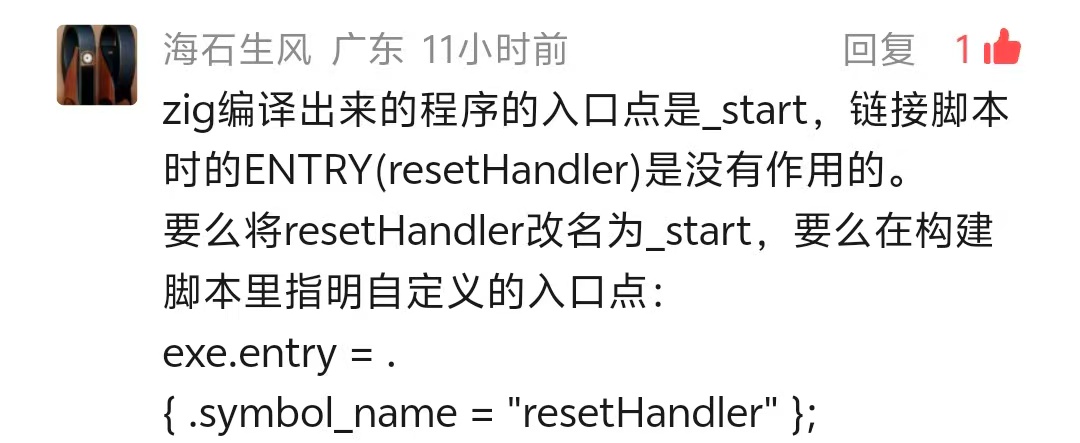
此外非常感谢微信用户 @海石生风 打的补丁:
ta 所说的 _start 为入口点是错误的(我们这里不是,但如果自己写个文件 pub fn main() void {}, 然后再 zig build-exe file.zig 之后分析出来就是,因为引入了上面提到的几个 crt 文件),exe.entry = . { .symbol_name = "Reset_Handler" };,_mainCRTStartup 这套初始化逻辑重定向,_mainCRTStartup 的分析见附录 .
Zig lld 并不总是遵守我们的 ld 脚本,这点挺让人讨厌的。
此外我们来看下两个文件的大小吧:
1 2 3 4 5 6 7 ❯ size $zig_elf text data bss dec hex filename 13192 1640 496 15328 3be0 zig-out/bin/zig-test.elf ❯ size $make_elf text data bss dec hex filename 8148 12 1692 9852 267c HAL_Driver/build-make/zig-test.elf
可以发现大概大了 5KB 左右,如果你的板子内存杠杠的话用 Zig 完全没问题:
1 2 3 4 Python 3.14 .2 (main, Jan 2 2026 , 14 :27 :39 ) [GCC 15.2 .1 20251112 ] on linux Type "help" , "copyright" , "credits" or "license" for more information.>>> (15328 - 9852 ) / 1024 5.34765625
加入 Zig 代码 接下来我们来写 src/main.zig:
1 2 3 4 5 6 7 8 9 10 11 12 13 14 const hal = @cImport ({ @cDefine ("STM32G431xx" , {}); @cDefine ("USE_HAL_DRIVER" , {}); @cInclude ("main.h" ); }); export fn zigMain () void { while (true ) { hal.HAL_GPIO_WritePin (hal.LED1_GPIO_Port, hal.LED1_Pin, hal.GPIO_PIN_SET); hal.HAL_Delay (1000 ); hal.HAL_GPIO_WritePin (hal.LED1_GPIO_Port, hal.LED1_Pin, hal.GPIO_PIN_RESET); hal.HAL_Delay (1000 ); } }
然后再修改 Core/Src/main.c 并启用 BUILD_BY_ZIG 宏:
1 2 3 4 5 6 7 #define BUILD_BY_ZIG
接下来运行 zig build 并烧录二进制文件,可以观察到 LED1 闪烁。
1 2 3 4 5 6 7 8 9 10 11 12 13 14 15 16 17 18 19 20 21 22 23 24 25 26 27 28 29 30 31 32 ❯ /usr/bin/openocd -s $(pwd ) -f interface/cmsis-dap.cfg -f target/stm32g4x.cfg -c "program $(pwd) /zig-out/bin/zig-test.elf " -c "reset run" -c "exit" Open On-Chip Debugger 0.12.0-01004-g9ea7f3d64-dirty (2025-11-12-08:18) Licensed under GNU GPL v2 For bug reports, read http://openocd.org/doc/doxygen/bugs.html Info : auto-selecting first available session transport "swd" . To override use 'transport select <transport>' . Info : CMSIS-DAP: SWD supported Info : CMSIS-DAP: JTAG supported Info : CMSIS-DAP: FW Version = 1.0 Info : CMSIS-DAP: Interface Initialised (SWD) Info : SWCLK/TCK = 1 SWDIO/TMS = 1 TDI = 1 TDO = 1 nTRST = 0 nRESET = 1 Info : CMSIS-DAP: Interface ready Info : clock speed 2000 kHz Info : SWD DPIDR 0x2ba01477 Info : [stm32g4x.cpu] Cortex-M4 r0p1 processor detected Info : [stm32g4x.cpu] target has 6 breakpoints, 4 watchpoints Info : starting gdb server for stm32g4x.cpu on 3333 Info : Listening on port 3333 for gdb connections [stm32g4x.cpu] halted due to debug-request, current mode: Thread xPSR: 0x01000000 pc: 0x08000468 msp: 0x20008000 ** Programming Started ** Info : device idcode = 0x20036468 (STM32G43/G44xx - Rev 'unknown' : 0x2003) Info : RDP level 0 (0xAA) Info : flash size = 128 KiB Info : flash mode : single-bank Warn : Adding extra erase range, 0x080033f8 .. 0x080037ff Info : device idcode = 0x20036468 (STM32G43/G44xx - Rev 'unknown' : 0x2003) Info : RDP level 0 (0xAA) Info : OTP size is 1024 bytes, base address is 0x1fff7000 Warn : no flash bank found for address 0x2000005c ** Programming Finished **
现象如下面视频:
附录 对链接过程和内存分配的更加细致的观察 现在我们知道了 ENTRY 指定了程序的入口为 Reset_Handler,Reset_Handler 是程序的入口地址,build.zig 里面已经禁用了)
1
2
3
4
5
❯ $aod -S $zig_elf | grep -i 20 "08000250" 08000250 <_mainCRTStartup>:
而在 Makefile 编译的版本中,就的的确确是 Reset_Handler 在文件入口处:
1 2 ❯ $aod -S $make_elf | grep -i "08001ba8" 08001ba8 <Reset_Handler>:
由于 Reset_Handler 就在汇编启动文件中躺着,我们也可以来看下是什么情况:
1 2 3 4 5 6 7 8 9 10 11 12 13 Reset_Handler: ldr r0, =_estack mov sp, r0 /* set stack pointer */ /* Call the clock system initialization function.*/ bl SystemInit /* Copy the data segment initializers from flash to SRAM */ ldr r0, =_sdata ldr r1, =_edata ldr r2, =_sidata movs r3, #0 b LoopCopyDataInit
可以看到它做的事情就是初始化堆栈,_mainCRTStartup 所做的事情一致。SystemInit 为下一步做准备。
/* Copy the data segment initializers from flash to SRAM */
这也是我们上面分析出来错误的一环,可以得知默认行为是会将 _sdata 等字段从 Flash 复制到 RAM,而我们的 .init_array 和 .fini_array 由于没有显式声明导致读取了 RAM 的垃圾值。
而通过对 _mainCRTStartup 的进一步抓包,我们可以观察到:
1 2 3 4 5 6 7 8 9 10 11 12 13 14 15 16 17 18 19 20 21 22 23 24 25 26 27 28 29 30 31 32 33 34 35 36 37 38 39 40 41 42 43 ❯ $aod -S $zig_elf | grep -i -A 42 "08000250" 08000250 <_mainCRTStartup>: 8000250: 4b17 ldr r3, [pc, 8000252: 2b00 cmp r3, 8000254: bf08 it eq 8000256: 4b13 ldreq r3, [pc, 8000258: 469d mov sp, r3 800025a: f7ff fff5 bl 8000248 <_stack_init> 800025e: 2100 movs r1, 8000260: 468b mov fp, r1 8000262: 460f mov r7, r1 8000264: 4813 ldr r0, [pc, 8000266: 4a14 ldr r2, [pc, 8000268: 1a12 subs r2, r2, r0 800026a: f000 f878 bl 800035e <memset> 800026e: 4b0e ldr r3, [pc, 8000270: 2b00 cmp r3, 8000272: d000 beq.n 8000276 <_mainCRTStartup+0x26> 8000274: 4798 blx r3 8000276: 4b0d ldr r3, [pc, 8000278: 2b00 cmp r3, 800027a: d000 beq.n 800027e <_mainCRTStartup+0x2e> 800027c: 4798 blx r3 800027e: 2000 movs r0, 8000280: 2100 movs r1, 8000282: 0004 movs r4, r0 8000284: 000d movs r5, r1 8000286: 480d ldr r0, [pc, 8000288: 2800 cmp r0, 800028a: d002 beq.n 8000292 <_mainCRTStartup+0x42> 800028c: 480c ldr r0, [pc, 800028e: f000 f800 bl 8000292 <_mainCRTStartup+0x42> 8000292: f000 f86d bl 8000370 <__libc_init_array> 8000296: 0020 movs r0, r4 8000298: 0029 movs r1, r5 800029a: f000 f90f bl 80004bc <main> 800029e: f000 f88b bl 80003b8 <exit > 80002a2: bf00 nop 80002a4: 00080000 .word 0x00080000 ... 80002b4: 2000005c .word 0x2000005c 80002b8: 2000024c .word 0x2000024c ...
不过由于 Zig 的入口点是 _mainCRTStartupENTRY, zig lld 有自己的想法),_mainCRTStartup),
1 2 3 4 5 6 7 8 9 10 11 12 13 14 15 16 17 18 19 08000444 <frame_dummy>: 8000444: b508 push {r3, lr} 8000446: 4b05 ldr r3, [pc, #20] @ (800045c <frame_dummy+0x18>) 8000448: b11b cbz r3, 8000452 <frame_dummy+0xe> 800044a: 4905 ldr r1, [pc, #20] @ (8000460 <frame_dummy+0x1c>) 800044c: 4805 ldr r0, [pc, #20] @ (8000464 <frame_dummy+0x20>) 800044e: f000 f800 bl 8000452 <frame_dummy+0xe> 8000452: e8bd 4008 ldmia.w sp!, {r3, lr} 8000456: f7ff bfcf b.w 80003f8 <register_tm_clones> 800045a: bf00 nop 800045c: 00000000 .word 0x00000000 8000460: 2000019c .word 0x2000019c 8000464: 08000248 .word 0x08000248 08000468 <Reset_Handler>: .section .text.Reset_Handler .weak Reset_Handler .type Reset_Handler, %function
注意 frame_dummy 这个函数并没有 bl 到 Reset_Handler 下面的函数,_mainCRTStartup 和默认的 Reset_Handler。
但这里唯一无法解释的是为什么不会直接从:_mainCRTStartup 的 bl 80004bc <main> 开始一路执行到结束?
Zig 语言的一些介绍 和 Python 的 import this 一样,Zig 也有自己的 Zig 之禅。
1 2 3 4 5 6 7 8 9 10 11 12 13 14 15 ❯ zig zen * Communicate intent precisely. * Edge cases matter. * Favor reading code over writing code. * Only one obvious way to do things. * Runtime crashes are better than bugs. * Compile errors are better than runtime crashes. * Incremental improvements. * Avoid local maximums. * Reduce the amount one must remember. * Focus on code rather than style. * Resource allocation may fail; resource deallocation must succeed. * Memory is a resource. * Together we serve the users .
对于 Zig 来说,我个人认为最重要的一点是官网注明的:
No hidden control flow.
没有隐式控制流。
No hidden memory allocations.
没有隐式内存分配。
No preprocessor, no macros.
没有预处理,没有宏。
没有宏这点我持保留意见,comptime 的概念,
不过 C 的宏(尤其是宏函数)有的时候确实会造成一些灾难,
以及对于 C/C++ 生态(如果导入源码或者 vcpkg 也能算生态的话)的无缝衔接:
Use Zig as a zero-dependency, drop-in C/C++ compiler that supports cross-compilation out-of-the-box.
将 Zig 作为零依赖、即插即用的 C/C++ 编译器使用,支持开箱即用的跨编译。
Leverage zig build to create a consistent development environment across all platforms.
利用 zig build 创建跨所有平台的统一开发环境。
Add a Zig compilation unit to C/C++ projects, exposing the rich standard library to your C/C++ code.
向 C/C++ 项目添加 Zig 编译单元,将丰富的标准库暴露给你的 C/C++ 代码。
Zig 有个 @cImport() 和 @cInclude() 函数,可以导入 C 头文件,
显式优于隐式的设计思想是我个人觉得 Zig 非常优秀的一点,这意味着下面的 C 语言行为将不复存在:
1 2 3 4 5 6 7 8 9 10 11 12 13 14 15 16 17 18 19 20 21 22 #include <stdio.h> int return_int () { char a = '0' ; return a; } int main () { int uninit_var; printf ("未初始化变量值: %d\n" , uninit_var); if (uninit_var > 10 ) { printf ("条件成立\n" ); } int a = return_int(); printf ("return_int() 返回值: %d\n" , a); return 0 ; }
1 2 3 4 5 6 7 8 9 10 11 12 ❯ gcc -Wall -Wextra -o test test.c test.c: 在函数‘main’中: test.c:11:5: 警告:‘uninit_var’未经初始化被使用 [-Wuninitialized] 11 | printf ("未初始化变量值: %d\n" , uninit_var); // 编译器警告 | ^~~~~~~~~~~~~~~~~~~~~~~~~~~~~~~~~~~~~~~~~~ test.c:10:9: 附注:‘uninit_var’在此声明 10 | int uninit_var; | ^~~~~~~~~~
又或者是一些其他有的没的,
更多详细的内容请参考官方文档 。
下面是一段 Zig 的示例代码(摘自官网):
1 2 3 4 5 6 7 8 9 10 11 12 13 14 15 16 17 18 19 20 21 22 23 24 const std = @import ("std" );const parseInt = std.fmt.parseInt;test "parse integers" { const input = "123 67 89,99" ; const gpa = std.testing.allocator; var list: std.ArrayList (u32 ) = .empty; defer list.deinit (gpa); var it = std.mem.tokenizeAny (u8 , input, " ," ); while (it.next ()) |num| { const n = try parseInt (u32 , num, 10 ); try list.append (gpa, n); } const expected = [_]u32 { 123 , 67 , 89 , 99 }; for (expected, list.items) |exp, actual| { try std.testing.expectEqual (exp, actual); } }
以及我自己在做的玩具 Zig 项目:
1 2 3 4 5 6 7 8 9 10 11 12 13 14 15 16 17 18 19 20 21 22 23 24 25 26 27 28 29 30 31 32 33 34 35 36 37 38 39 40 41 42 43 44 45 46 47 48 49 50 51 52 53 54 55 56 57 58 59 60 61 62 63 64 65 66 67 68 69 70 71 72 73 74 75 76 77 78 79 80 81 82 83 84 85 86 87 88 89 90 91 pub const ColorType = enum { R, G, B };pub const ColorError = error{ NotExpectedBufferSize, }; pub const Color = struct { R: u8 = 0 , G: u8 = 0 , B: u8 = 0 , MaxColorValue: u8 = 255 , pub fn init () Color { return .{}; } pub fn setMaxColorValue (self : *Color, value: u8 ) void { self .MaxColorValue = value; } pub fn setPixel (self : *Color, color: ColorType, value: u8 ) void { switch (color) { ColorType.R => self .R = value, ColorType.G => self .G = value, ColorType.B => self .B = value, } } pub fn toString (self : Color, buffer: []u8 ) !void { if (buffer.len != 14 ) { log.err ("Expected a buffer: [14]u8, got {d}" , .{buffer.len}); return ColorError.NotExpectedBufferSize; } _ = try fmt.bufPrint (buffer, "{d:3} {d:3} {d:3} " , .{ self .R, self .G, self .B }); } pub fn fromArray (self : *Color, pixelUnit: []const u8 ) !void { const colorSequence = [_]ColorType{ .R, .G, .B }; for (pixelUnit, 0 ..) |origin, currentColorIdx| { var value: u8 = origin; if (value > self .MaxColorValue) { log.warn ("Got a number bigger than MaxColorValue:\n\t" ++ "Number: {d}, MaxColorValue: {d}\n" ++ "Set to MaxColorValue." , .{ value, self .MaxColorValue }); value = self .MaxColorValue; } self .setPixel (colorSequence[currentColorIdx], value); } } test setMaxColorValue { var color = Color.init (); color.setMaxColorValue (20 ); try testing.expect (color.MaxColorValue == 20 ); } test toString { var color = Color.init (); var arr = [_]u8 { 255 , 255 , 20 }; var buf: [14 ]u8 = undefined; try color.fromArray (&arr); try color.toString (&buf); try testing.expect (mem.eql (u8 , &buf, "255 255 20 " )); var buf2: [1 ]u8 = undefined; const err = color.toString (&buf2); try testing.expectError (ColorError.NotExpectedBufferSize, err); } test fromArray { var color = Color.init (); var arr = [_]u8 { 255 , 255 , 20 }; try color.fromArray (&arr); try testing.expect (color.R == 255 and color.G == 255 and color.B == 20 ); } };
此外 Zig 作者 Andrew Kelley 的野心十分大,
这里需要注意的是,
1.0 will come out when it’s “ready” (quoted from Andrew Kelley). The Zig core team doesn’t want to rush to 1.0 and wants to ensure everything is great (so that they regret as few decisions as possible when the first “language stable” release is actually out and you can’t really change stuff anymore).
这意味着 1.0 大概是遥遥无期的。issue
图片链接:
参考资料:

.png)
.png)